
Methods for Control of a Robotic Hand
- Python
- ROS
- HTML
- CSS
- Javascript
- SVG
- Computer Vision
- Machine Learning
- BCIs
BEng dissertation project involving the use of a ‘qb Softhand research’ and various methods for its control including a look at a possible method for a Brain Computer Interface. This project also includes stimuli animated resources to aid the collection of data for training a model for a BCI.
This is an abridged version of the original report.
Abstract
Robotic analogues for human limbs can be seen in use in fields including manufacturing and prosthetics. Methods for controlling prostheses vary based on use-case however a particularly interesting technology is neuroprosthesis which makes use of cortical signals to control the movement of robotic limbs. This extraction and analysis of signals is known as a Brain Computer Interface (BCI) and is the main mechanism for enabling movement. This project aimed to implement and assess the use of EEG signals as well as computer vision models for hand movement and face movement to control a robotic hand. In this project a system is produced allowing for the use of multiple computer vision models to control a robotic hand. It was found that the implementation of computer vision models created, was too slow to be used effectively for prostheses, however the results of the models were precise enough. Due to hardware obtainment limitations the EEG portion of this project was not possible. It is hoped that this work can be continued in order to make a full implementation of the EEG portion of the project. Future work could also work on further increasing the precision of results and reducing any shakiness.
Introduction
The primary aim for this project is to create multiple systems for the control of a robotic hand and then analyse their efficacy. This project aims to consider the effectiveness of each system in real-world use cases such as prosthetics and industrial applications. This title and aim of this project have changed since it was started. The original name for this project was ‘Robotic Hand Control using EEGs’ however this was changed at late point in the project once it was found that there would be issues using the hardware. At this point a contingency plan was launched which involved the use of computer vision as a means for control rather than EEG signals. This contingency plan included the control of the robotic hand using computer vision for hand mimicking and facial emotion.
Background
Computer Vision
Computer vision is the ability for computers to be able to derive useful information from visual inputs. [2] Research for computer vision started in 1959, when scientists found that the most basic forms of image processing start with the identification of hard edges or lines. This has since evolved into object recognition and now computers can even identify the constituent parts of objects. This is possible due to deep learning (multi-layered machine learning) and convolutional neural networks which break images down into pixels for performing mathematical operations on.
Electroencephalography
In 1875, Richard Caton, upon learning about David Ferrier’s discovery of electrical signals in the brain, employed a galvanometer to observe and quantify electrical currents present on the surfaces of animal brains [3]. Nevertheless, it was only in 1924 that Hans Berger, a German psychiatrist who possessed knowledge of Caton’s endeavours, demonstrated that the human brain also employs electrical waves to transmit signals. Notably, Berger conducted the inaugural recording of human brain activity known as an electroencephalogram (EEG) [4].
Modern day electroencephalography makes use of electrode caps which when in contact with the scalp, can be used to capture electrical signals produced by the brain to produce EEGs. It is important to note that electric activity is not localised on the surface of the scalp and therefore can be picked up my multiple electrodes however it can be deduced from the strength of a signal what locality it originated from. The challenge of EEG analysis is to separate the many electrical signals occurring in the brain and identify activity of interest.
Objectives
It is important to note that the current aims and objectives of this project have shifted due to the hardware limitations found during the project and the contingency plan put in place instead. The main aims for this project can be broken down into simple steps which are assigned criteria so that it can be assessed whether or not these objectives have been met by the end of the project:
- Using a webcam video stream, identify what percentage closed a hand is. Considered met if an application has been created that can identify, with good accuracy, how closed a hand is.
- Using a webcam video stream, classify different facial emotions. Considered met if an application has been created that can identify, with good accuracy, at least three facial emotions.
- Read data into a computer from an EEG system. Considered met if EEG data can be collected/stored on a computer and preferably displayed on some graph (V-t).
- Drive the robotic hand to change to multiple basic states, e.g. closed fist, open hand. Considered met if the hand can be programmed to change state between to at least two desired positions.
- Assess the accuracy of the system and potential applications. Considered met if the final report for this project contains information about the accuracy of the system and potential applications.
The above points are all considered core aims. Depending on time and complexity constraints, further stretch targets may also be met:
- Recreate the data collected using the EEG system. Considered met if the recreated data can be collected/stored on a computer and preferably displayed on some graph (V-t).
- Accurately interpret the recreated EEG data and move the robotic hand together in real time. Considered met if the recreated data can be used to timely move the robotic hand. This includes classifying any states correctly >80% of the time and the total response of the system taking less than 100ms.
Implementation
The implementation of this project was tackled using separate modules. These modules were ROS, test-video, and vision. Before the contingency plan was implemented there was also going to be an EEG module as well however since no analysis of signals was completed, this module was removed from the project.
ROS
The ROS module was an early part of the project to be implemented due to lack of availability of the EEG cap and its relative isolation from the rest of the code. This module is produced as a standalone component designed to be easily integrated into any other script within the project.
Communication with the robotic hand was achieved using ROS 1 Noetic which only is only available on certain Linux operating systems therefore Ubuntu 20.04 LTS was installed on the machine used for running this project. ROS could then be installed by adding ROS packages to the APT sources list and installing using the apt install command. The final step in installation was to add a setup script to the .bashrc file so that catkin, the build system for ROS would be initialised every time a new terminal window was opened.
This project used a qbrobotics SoftHand 2 research robot. The SoftHand has 2 controllable motors: manipulation-joint used for pinching with thumb and index finger and synergy-joint used for opening the hand flat and closing the hand into a fist.
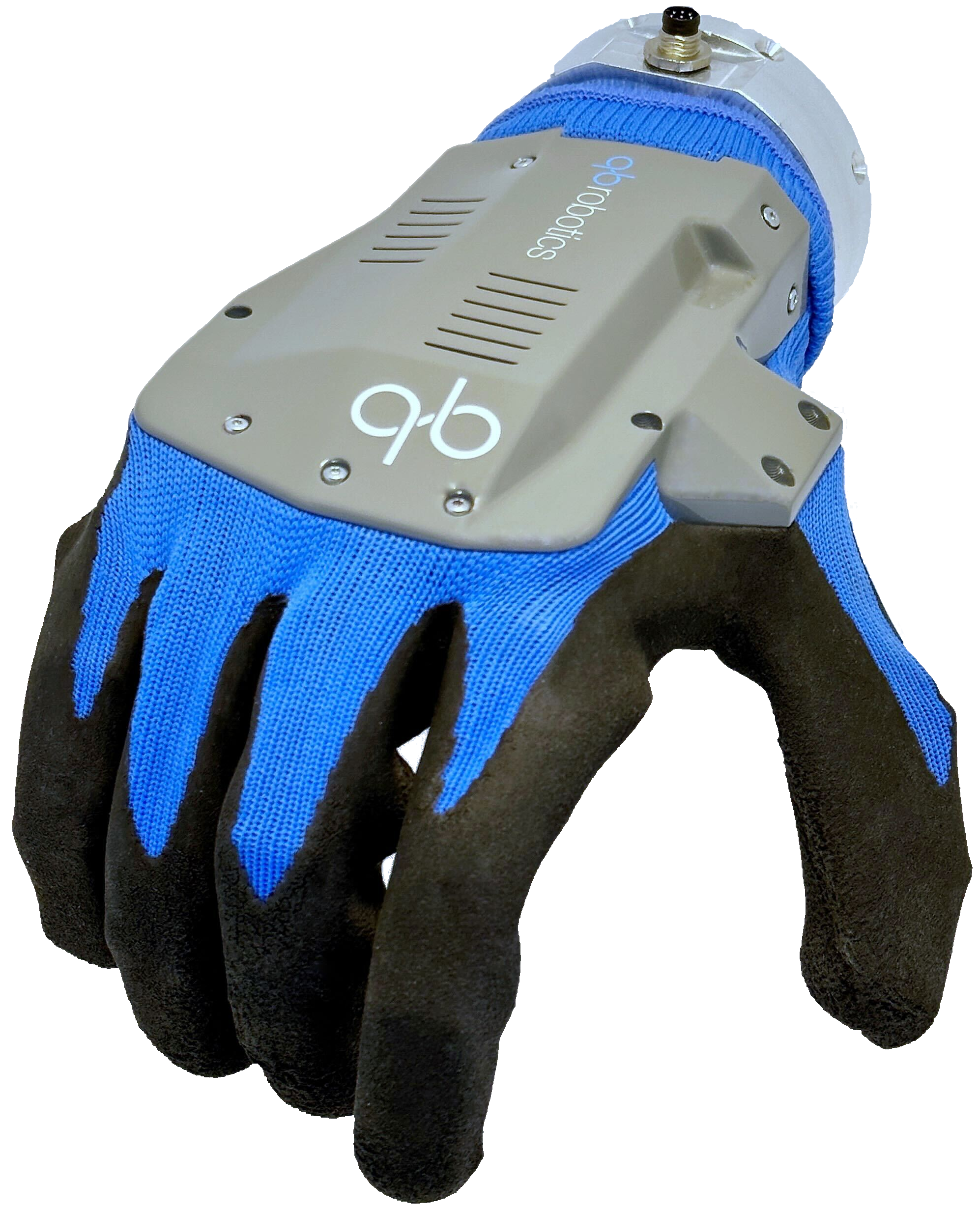 Figure 1: Image of the qbrobotics SoftHand Research
The robotic hand is set up to communicate with a ROS server. A class was written for controlling the robotic hand using ROS trajectories, which is a programmatic interface that sends commands to the ROS server. A simple method for control of the robotic hand was supplied at the start of the project. This has been retained in a modified state in the project directory as it is useful for running via the command line when setting up the SoftHand to check the working order of the connection.
The more complex control method contained in this module contains a class which has methods for control of the hand either by requesting a specific percentage of closure or by asking for small incremental movements. The percentage control is particularly useful for mimicking hand positions whereas the small incremental movements are intended for use with the facial emotion and EEG control methods.
In order to send messages to the ROS server, an object must be set up for asynchronously sending messages of a specific type (in this case JointTrajectory) to a specific ROS topic. Along with a node for running processes on. This class also sets a rate for which the program will try to fulfil, this program specifically attempts to send 5 messages a second. A new JointTrajectoryPoint is created where attributes for the point’s position can be set. This also requires that the velocity, acceleration, and effort values are also set however these are not used in this script. For the purposes of this project only the synergy joint is being manipulated however it is necessary to give some values for both joints. The position value of this joint ranges from 0 to 1 with 0 being flat open hand and 1 being closed into a fist. All values for joints and attributes not being used are set to 0.
This JointTrajectoryPoint is then added to a JointTrajectory object which contains the current timestamp (used for ordering messages as they come in) and the names of the joints that are to be manipulated. Finally, the JointTrajectory object can be ROS server and a sleep initiated to fulfil the 5Hz rate set at the beginning of the program.
vision
After identifying that the EEG path for this project might not have been available, multiple methods for computer vision control were decided upon. First, hand identification would be used and then facial identification.
Hand stream identification
This approach was selected and executed first for its ease of verification and implementation. The first version of hand identification was conducted on single images, using the model provided on the MediaPipe website. This version of the code did not attempt to calculate how closed the hand was and instead was used to just test the hand skeleton could be identified.
Following the single image identification program, the video stream version of the code used a built-in model from Google’s MediaPipe library [5], in particular from the Solutions module. This version of the code attempts to calculate what percentage the hand is closed using relative comparisons between hand landmarks.
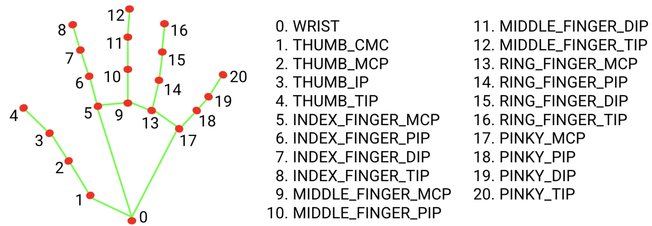 Figure 2: Hand landmarks as specified in MediaPipe’s documentation
The hand webcam stream code uses the hand landmarks to find the ratio between the palm-to-wrist distance and fingertip-to-wrist distance which gives a good estimate for how closed the hand is. It is necessary to use ratios rather than absolute distances since it allows for the hand to be a varied distance from the camera and the method still work. This value can then be displayed to the user on the image using the OpenCV library’s putText method.
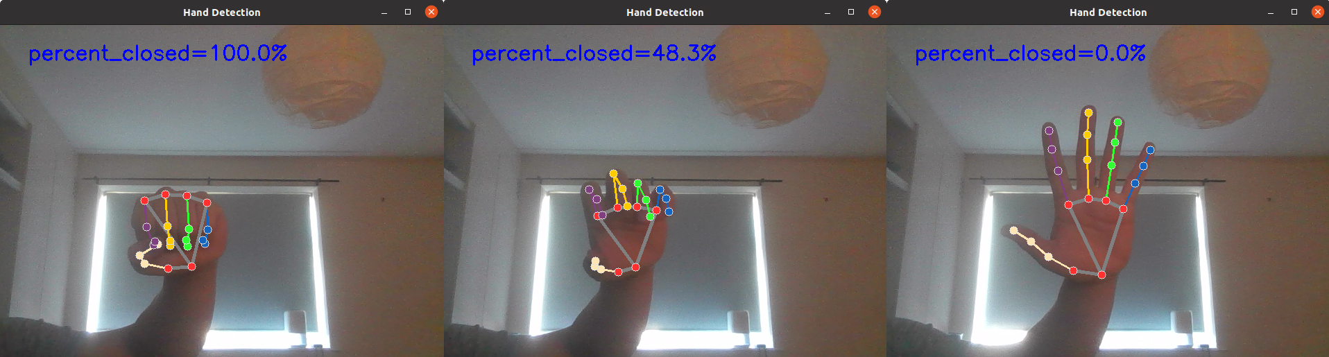 Figure 3: Hand detection at varying levels of being closed
The value representing hand closedness can then be passed through to the ROS code which can subsequently move the SoftHand mimicking the user’s movement. The script accommodates running this code both with and without the SoftHand connection using a parameter that specifies whether the hand is connected or not.
Advantages of using hand detection as a method for control include easy comparison between SoftHand movement and real hand input and simple implementation. However, drawbacks include deviation from the initial use case of a device applicable to prosthetics, slower performance due to prolonged processing times from computer vision detection, and minor jittering stemming from slightly unstable closedness values.
Figure 4: Visible latency shown in live demonstration video
Facial emotion stream classification
The second stage of the contingency plan involved the use of facial emotion recognition to control the robotic hand. This method was chosen since it can control the robotic hand without the need for the movement of any other limbs. Since there isn’t a pre-existing model for emotion recognition, a model would have to be trained.
Generate Data
The first step in this process is to get a dataset for training the emotion recognition model on. After looking for some open-source facial emotion training data it was determined that there was not any adequate training sets available online. Most of the sets that were found were too low resolution for use in this project. After finding a method for generating facial emotion datasets [6], a script could be made to closely follow the process.
As a requirement for this method, a Cuda enabled GPU is necessary. It is possible to generate the images without GPU acceleration however it would likely take a very long time. The method for generating the images uses the Diffusers library from HuggingFace.
The method involved first creating a pipeline object that could accept prompts and enabling Cuda for it. Directories were then made for each of the facial expressions to be generated. Lists of parameters could then be defined for ethnicity, gender, and a dictionary defined for the three emotions to be detected: happy, neutral, and sad. For a specified number of images, an image of each emotion was created with a random selection of ethnicity and gender. Once created, the image could be saved to the respective emotion folder. This process can take a long time (30 minutes on a Nvidia GeForce RTX 4060 Ti).
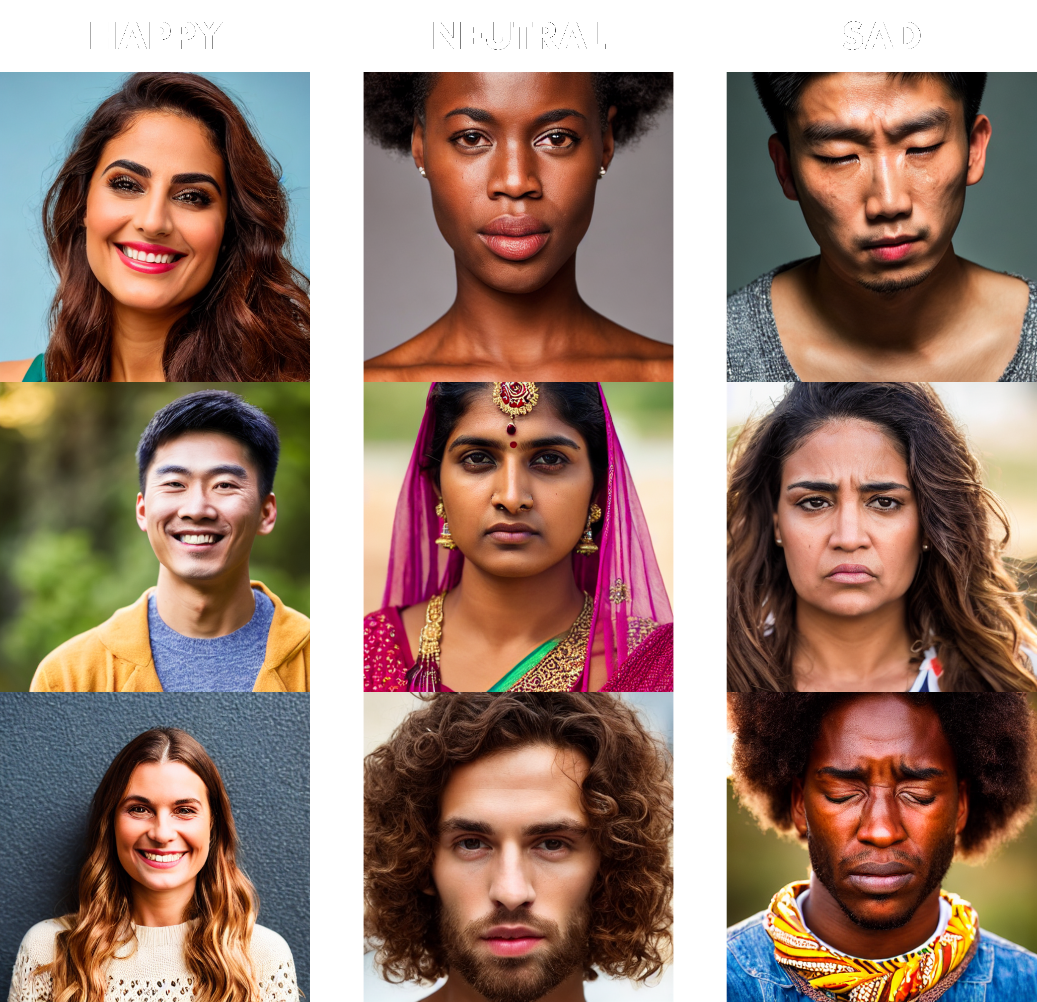 Figure 5: Sample of the generated training data
The quality of the output images from the image generation is reasonably good as shown in fig. 6 however there are noticeable oddities on closer examination. The main issues are warped eyes and teeth however this should not affect the quality of the model as the correct general facial shapes are present. It is interesting to note that the model seemed to generate better happy faces than sad faces: this could be due to the prompts given or possibly due to some bias in the model.
Train Model
The next step is to use the generated dataset to train a classification model. The method found for this [7] uses scikit-learn in order to train a decision tree using a random forest classifier. Decision Trees (DTs) are a supervised learning method used in classification models. A DT is designed to predict the value of an input by using simple decision rules. [8] DTs can be represented in a tree structure. Data in this project uses a random forest classifier provided by the scikit-learn python library. [9] A random forest classifier uses many DTs together and chooses the most common result. A benefit of random forest classification is that it reduces overfitting (remembering training data rather than making predictions on future data).
In order to train the model a helper function is needed for getting the landmarks in a given face. This uses MediaPipe’s Solutions module. The process involves reading the input image then creating a face landmark identification object. Next, using the landmark identification object the landmarks of the given image are retrieved. The locations of all these landmarks are then normalised so that they can be compared to each other regardless of the location of the face in the image. This list of landmarks is then returned.
The method for training the model starts with preparing the data. This is achieved by reading each image in the dataset and identifying the facial landmark. A check is then done to ensure that all 1404 coordinate values are present in the returned facial landmarks. This ensures the face is fully contained within the image and helps with the quality of data. A label is then attached to each set of landmarks to indicate which emotion it represents. Finally, all landmarks are saved as a text file in the form of a NumPy array.
The next stage of the process is the training of the model. The script first loads the text file generated in the previous step into memory. The landmark coordinates are then separated from the emotion labels. Next, the skikit_learn method, train_test_split, is used to take a random sample of the test data with the correct associated label for training and testing the accuracy of the model. A RandomForestClassifier object can now be created and trained using the data obtained from train_test_split. Finally, the model, which is a Python object, can be saved to disk. This is possible due to the pickle module which allows for the saving of Python callables.
Facial Stream
Now that the classification model has been trained, it can be used in making predictions for new faces. Firstly, the callable model saved can be loaded once again using the pickle module. The webcam can then be opened for capture where a frame will be taken, landmarks identified, and a prediction made using the callable model. Provisions have been made for if the face is not in frame with a try-except block which can set the output to the ‘Face Not Found’ option. Finally, the result can be displayed on the image using OpenCV’s putText method.
Integration with the SoftHand was never tested with this model due to time constraints however if it had of been tested a happy emotion would have opened the hand whilst making a sad expression would have closed the hand. A neutral expression would have kept the hand stationary. This was a purposeful choice as most of the time you would want to keep the hand steady and this is easiest done when linked to a neutral face.
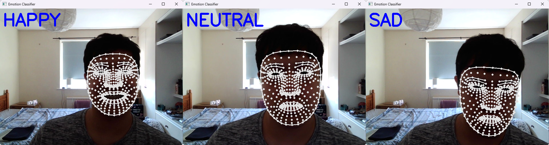 Figure 6: Example of each detectable emotion
An advantage of this method includes the fact that it doesn’t require the movement of any limbs. However, it has several disadvantages: classification is not perfect, which can result in unintended hand movements from accidently making the wrong facial expression, and it is slow due to the need to run a prediction on a classification model constantly.
test-video
In order to collect the EEG data that would later be analysed, stimuli videos first needed to be created. This was the first module developed in the project, prior to gaining access to the SoftHand and before any contingencies were established. 3 videos each designed to test for specific brain responses were created by making looping animations using HTML, CSS, JavaScript/jQuery, and SVG. These animations were programmatically generated to enable quick creation of precise shapes and patterns, easily facilitate timing adjustments, and allow dynamic resizing of the SVG canvas for various screen sizes. The SVG images were designed to be displayed optimally on multiples of 1080p, which is the most common resolution for PCs [10].
Visual Evoked Potential (VEP test)
VEP is a common EEG test used to assess the condition and latency of the neural pathways between the optical nerve and the visual cortex in the occipital lobe at the back of the brain. For the purposes of this project, the test is intended as a control to ensure that the EEG data collected is of a high enough quality. The test consists of a black and white checkered pattern that continuously alternates colours with a stationary red dot in the middle, at which the participant is instructed to look.
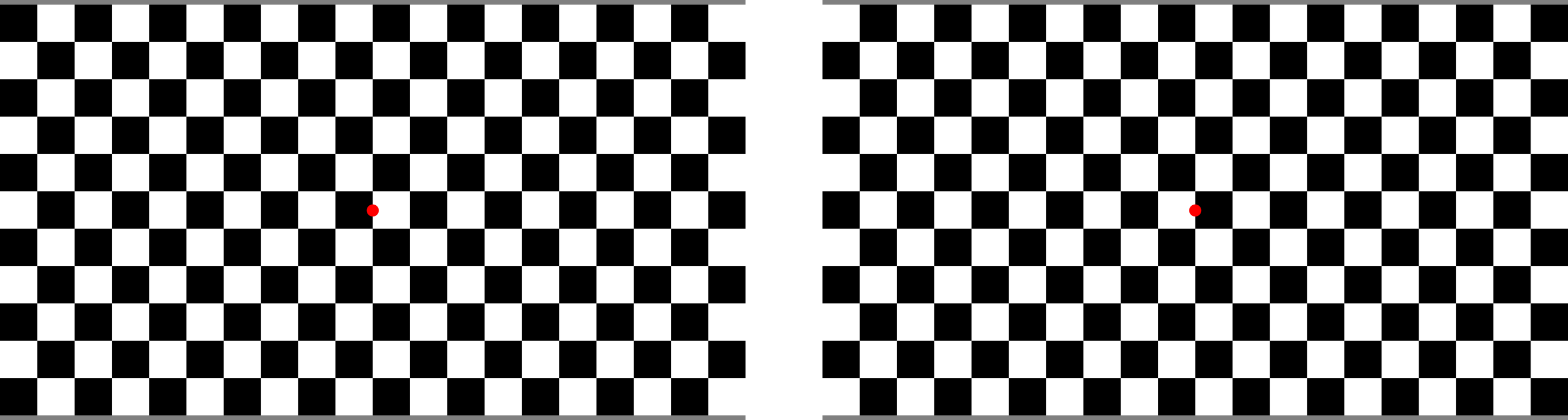 Figure 7: Two frames of the VEP test video
The creation of this effect involves the use of 2x2 grids of alternating black and white squares generated using the SVG pattern feature. A jQuery function is used to check each square’s colour and switches it to the opposite colour. JavaScript’s setInterval function is used to ensure that the wait between each interval is constant (the default for this test is set to 1.5s). Due to the simplicity and concision of the jQuery code for this test, it is stored directly in the HTML file rather than in a separate JavaScript file.
Continuous Hand Control Stimulus
As part of the hand control for this project, a standardised test was needed for collecting EEG data related to the continuous movement of the hand. The test consists of an animation where a blue square’s outline is enclosed by another blue square’s outline. Once the two outlines meet, the square is filled in with blue. After a short pause, a similar process occurs with a red circle, and this sequence loops indefinitely.
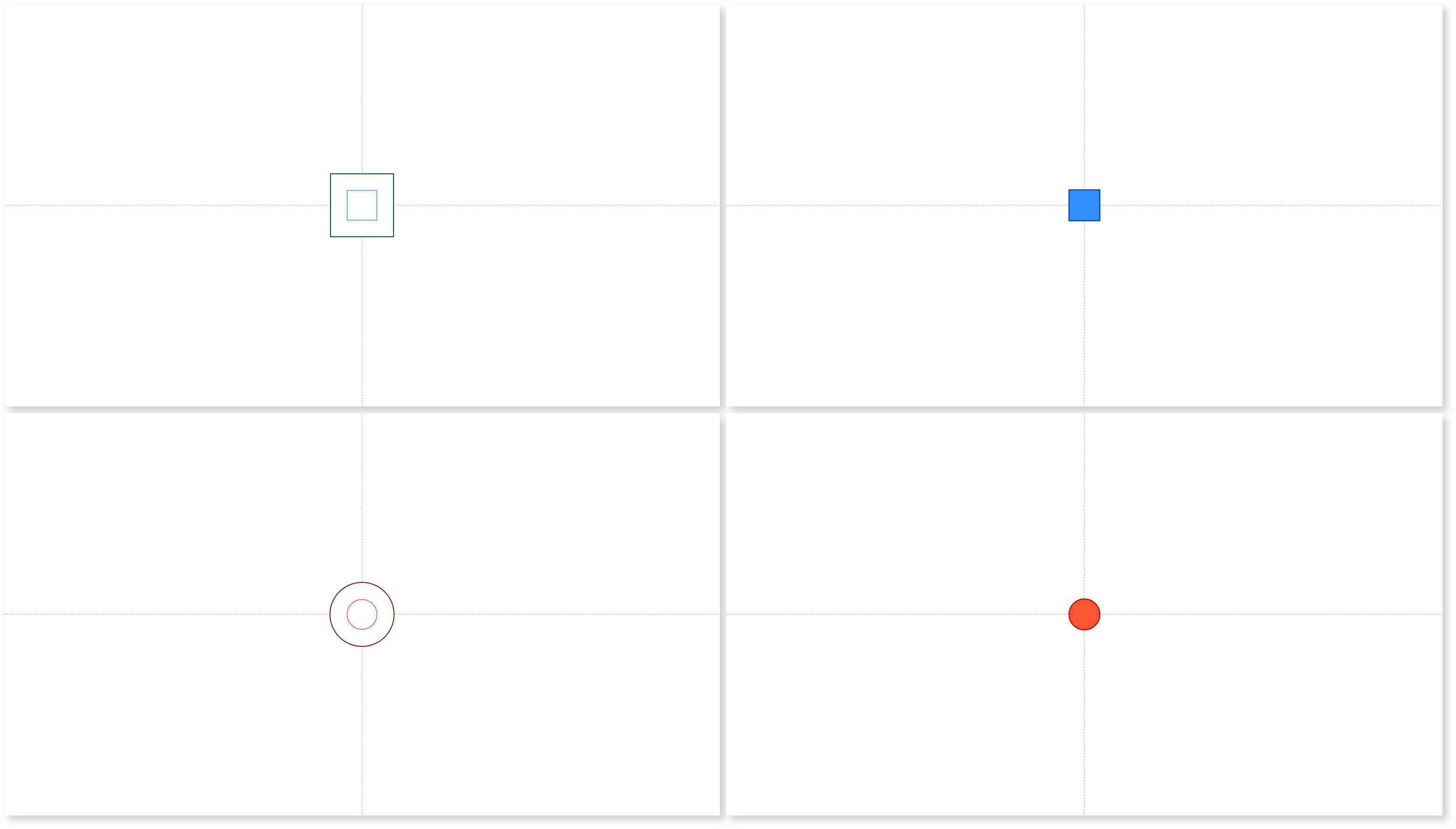 Figure 8: Four example frames from the continuous hand control test video
Participants are instructed to rest their hand palm up on a table in front of them. They are then to gradually close their hands as the outer red circle closes in, ensuring their hand is fully closed when the red circle fills. Conversely, they open their hand gradually as the outer blue square closes in, having their hands fully open by the time the blue square fills. Using both shape and colour differentiators allows the test to be accessible even to those with colour blindness and helps with association of a visual stimuli to a movement. The hope would be that this would trigger a response in both the visual and motor cortex.
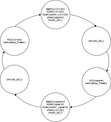 Figure 9: FSM for continuous hand control test video
The animation is implemented as a series of stages which are selected sequentially using a switch-case block operating like a finite state machine as can be seen in fig. 11. Each time a stage is completed the stage counter is incremented. A full cycle through this switch-case block represents a complete loop of the animation. To manage the wait functionality, a global count incrementing every frame is used since JavaScript’s setTimeout function does not block script execution, which would otherwise cause the animation to continue running during intended pauses.
General functions for show element, hide element, fill element, and empty element were created owing to shared attributes among all SVG shapes in this animation. However, specific functions were needed for shrinking and resetting the size of the outer square and outer circle. Since the circle element uses a centre x and y coordinate it doesn’t move when resized which means that the radius needs merely needs to be reduced each time and then once the radius gets to a specific size the stage counter will be incremented. The reset function only needed to set the outer circle’s radius to its initial radius which is obtained when the page loads. The square element, on the other hand, uses an x and y coordinate originating in at the top left of the square. This means that when the square is resized it appears to shrink towards the top left. To account for this the outer square needs to be shifted in the x and y direction, half the amount the square is shrunk. This also affects the reset functionality of the outer square where the x, y, width, and height properties all need to be reset using values taken at page load time.
Gradual Hand Control Stimulus
Since it was uncertain if continuous movement would be optimal for later EEG data analysis, a test video for the gradual movement of the hand was also created. This test features a number in the centre of the screen that counts up, with the word “ready” appearing on the left-hand side before each increment to prepare the participant for the next movement.
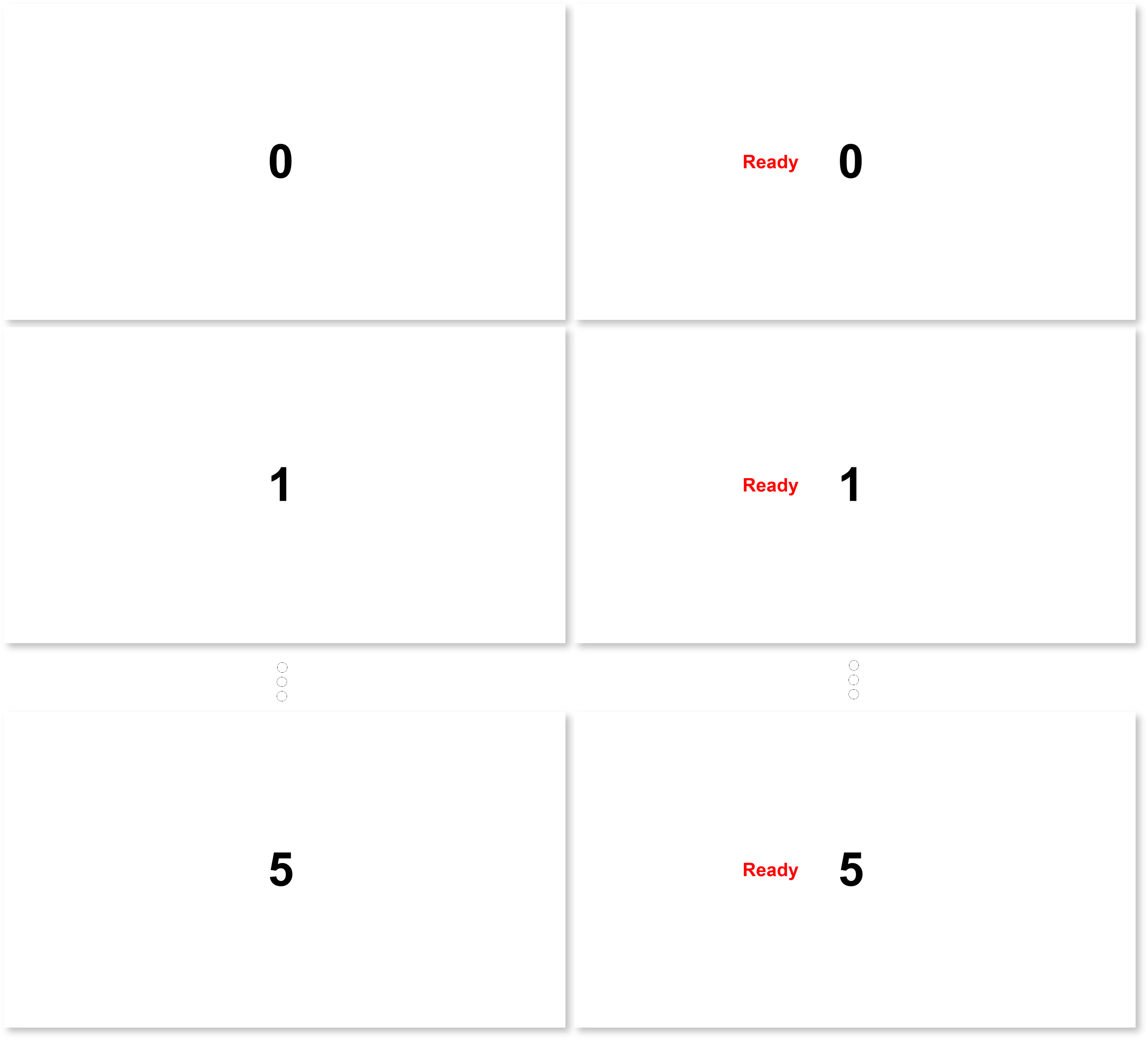 Figure 10: Example of frames from the gradual hand control test video
Participants are instructed to place the back of their hand once again on the table but this time in a closed fist. They are to associate each number being shown with a level of hand openness, with 0 being their hand in a closed fist and 5 being an open palmed hand. The animation for this test is implemented as a series of stages or ‘slides’, similar to the continuous hand control test the switch-case block can be visualised as a finite state machine seen in fig. 13.
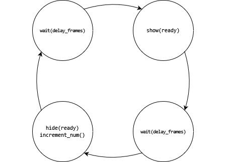 Figure 11: FSM for gradual hand control test video
The code for this test is simpler than that of the continuous hand control test, requiring only show and hide element functions along with the same aforementioned global wait function. Unlike the continuous hand control test, a full loop through the switch-case statement in this test does not represent a complete cycle of the animation but rather the code necessary to increment and display a single number.
References
[1] University of York, “Code of practice and principles for good ethical governance,” 10 May 2022. [Online]. Available: https://www.york.ac.uk/staff/research/governance/research-policies/ethics-code/. [Accessed 13 May 2024].
[2] IBM, “What is computer vision?,” [Online]. Available: https://www.ibm.com/topics/computer-vision. [Accessed 20 May 2024].
[3] W. Omerod, “Richard Caton (1842-1926): pioneer electrophysiologist and cardiologist,” Journal of Medical Biography, vol. 14, no. 1, pp. 30-35, 2006.
[4] L. F. Haas, “Hans Berger (1873-1941), Richard Caton (1842-1926), and electroencephalography,” Journal of Neurology, Neurosurgery, and Psychiatry, p. 9, 2003.
[5] C. Lugaresi, J. Tang, H. Nash, C. McClanahan, E. Uboweja, M. Hays, F. Zhang, C. Chuo-Ling, M. Yong, J. Lee, C. Wan-Teh, W. Hua, M. Georg and M. Grundmann, “MediaPipe: A Framework for Perceiving and Processing Reality,” in Third Workshop on Computer Vision for AR/VR at IEEE Computer Vision and Pattern Recognition (CVPR) 2019, CVPR, 2019.
[6] computervisioneng, “Creating an Emotion Recognition Synthetic Dataset with Python & Stable Diffusion,” 25 January 2024. [Online]. Available: https://github.com/computervisioneng/create-synthetic-dataset-emotion-recognition/. [Accessed 20 May 2024].
[7] computervisioneng, “emotion-recognition-python-scikit-learn-mediapipe,” 31 January 2024. [Online]. Available: https://github.com/computervisioneng/emotion-recognition-python-scikit-learn-mediapipe/. [Accessed 20 May 2024].
[8] scikit-learn, “1.10. Decision Trees — scikit-learn 1.4.2 documentation,” [Online]. Available: https://scikit-learn.org/stable/modules/tree.html. [Accessed 20 05 2024].
[9] F. Pedregosa, G. Varoquaux, A. Gramfort, V. Michel, B. Thirion, O. Grisel, M. Blondel, P. Prettenhofer, R. Weiss, V. Dubourg, J. Vanderplas, A. Passos, D. Cournapeau, M. Brucher, M. Perrot and E. Duchesnay, “Scikit-learn: Machine Learning in Python,” Journal of Machine Learning Research, vol. 12, pp. 2825-2830, 2011.
[10] StatCounter, “Desktop Screen Resolution Stats Worldwide,” April 2024. [Online]. Available: https://gs.statcounter.com/screen-resolution-stats/desktop/worldwide. [Accessed 20 May 2024].